NOTE: The following comes from our popular book, THE "SCREWDRIVER EXPERT'S" GUIDE TO PEAKING OUT & REPAIRING CB RADIOS. This is just a small sample of the useful information you'll find there. Check it out!
HOW TO WIRE ANY REGULAR OR POWER MIKE TO (ALMOST) ANY CB
This wiring discussion assumes that you have no schematic for the
radio, or no information for the mike.
There are three steps when wiring any new mike to your CB:
1. Determine which pin on the radio’s mike socket performs which function (TX, RX,
Audio, Ground) on the CB itself.
2. Determine which color wire on the new or repaired mike performs that same function.
3. Be able to neatly solder and insulate those wires on the corresponding pins of the new
plug.
Before you even start, you must know if the CB uses relay or electronic switching between
TX and RX. The obvious way is to look at the main chassis for a relay. Or
while listening to a signal, unplug the mike. If you can still hear something,
it’s relay switched. If the speaker goes dead but the S/RF meter still shows a
signal there, you have electronic or diode switching. If your CB only has a 3-pin
mike socket (Pearce-Simpson, some Robyns, etc.) this is a dead giveaway that the CB is
relay switched, because electronic switching requires at least four wires.
Since diodes are cheaper than relays, nowadays almost all CBs use them. Some old
23-channel AM, all old 23 channel SSB, and the first generation 40 channel SSB
(Cobra 138/139XLR, etc.) used relays. Today all rigs use electronic T/R
switching to save production costs.
Relay switching is generally easier to wire up, because you only need three connections:
Mike Audio, Ground, and the TX Keyline that energizes the relay when Grounded.
Electronic switching uses four wires: a common Ground, Mike Audio, TX Keyline that
switches to TX when Grounded, and RX speaker line that opens the speaker on TX to prevent
feedback squeal.
These three or four connections are regardless of the number of pins on the CB
socket. For example, if your CB has one of those female 5-pin or 6-pin DIN type
sockets, only three or four of the pins are actually used. Manufacturers use the
cheapest parts they can find. If they got a good deal on a million DIN sockets
they’ll build the radios with them, instead of the superior 4- or 5-pin male socket
with threaded coupling nut.
To begin, figure out which pin on the mike socket does what. You’ll need a real
antenna or a Dummy Load, a clip-lead or a piece of bare wire, and possibly an
Ohmmeter.
Method #1 — With the use of an Ohmmeter
WARNING: Turn the radio off when using an Ohmmeter; you can blow the
meter by accidentally applying voltage to it on a Resistance scale!
1. Use the Rx1 resistance range. Attach one test lead to the BLACK power wire coming from
the CB or slide mount, or the [–] pin on the DC socket of a base station radio.
On a base station where the DC power socket isn’t stamped with [+] and [–]
symbols, you’ll have to remove the cover. The inside of the DC socket will
often use the standard RED [+] and BLACK [–] wires to the chassis to guide you.
2. Leave one Ohmmeter lead on the BLACK or [–] wire or pin. Touch the other
Ohmmeter test probe to all the mike socket pins. You’ll find one or two pins
that make the meter deflect all the way over to 0W.
That indicates a DC short (i.e., continuity) between the BLACK power lead and the socket
pin you’re testing. In other words, this is the Ground. On a DIN type
socket, the holes are too small to get the test probe into, so you’ll need to jam a
bare wire into the socket holes as you proceed. Or probe from the inside of the
socket if you can reach the connections on it.
OK, you’ve already found the Ground or “common” connection.
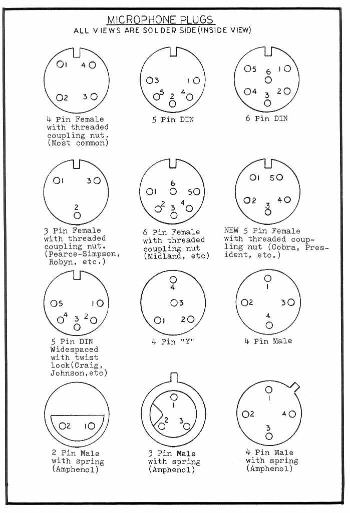
Immediately draw a sketch of the socket, using its notch as a reference point. Mark
the common Ground lead you just found. Figure 1 shows the pin numbering for
many of the most common CB mike sockets.
Note: When probing with a VOM on the mike pins of an electronically
switched radio, you may touch one pin that makes a small crackling noise in the CB
speaker. And it shows a few ohms of resistance. This is an obvious indication for
the RX line. Mark it on your sketch. You can also confirm this in Step #4
below.
3) Remove your Ohmmeter and turn on the CB. Now attach a
clip-lead or a piece of bare wire to the common pin you found in Step #2. Start
touching the other end of the wire or clip-lead to the remaining pins briefly and watch
what happens.
4) In an electronically switched radio, you’ll see the following: touching one pin
will operate the receiver speaker. Write it down. Another pin will key the
transmitter, which you’ll know by:
· the TX light glowing
· the Dummy Load/Modulation Light glowing brightly
· hearing a dead carrier on another CB tuned to the same channel.
This is the TX line. Write it down.
If you hear a squeal or buzzing sound, release the wires; you’ve either found
the Audio (Mike) line, or shorted the Mike line to the speaker (RX) line. Assuming
you found the common, the RX, and the TX in the steps above, the only thing left on the
typical 4-pin socket must be the Audio or Mike line, so you’re done!
On a 5- or 6-pin DIN socket, finding the Mike line will be slightly harder.
You’ll have to first find the TX line, as described above. Listen on another CB
tuned to the same channel while you touch the remaining socket pins with your fingers.
Then key the CB you're trying to wire; you’ll find that touching the Mike or
audio line causes a slight hum to be heard on the dead carrier when listening on the other
set.
5) In a relay switched CB, jumpering the common with the correct pin will key the
TX. You can then use the hum/fingers method above to find the Mike line. Some
older relay switched rigs used a small shielded cable between the mike socket and main
chassis, a dead giveaway that those are the Mike line and Ground.
The newer generation (Cobra 148GTL, Uniden Grant, Galaxy, RCI, etc.) uses electronic
switching exclusively (diodes are cheap!), and generally have 4-, 5-, or 6-pin mike
sockets. Only 4 wires are needed but bigger sockets often mean that more than
one pin may be grounded. In those models one ground is the common circuit ground and
the other is the earth or cabinet ground. This helps to break up potential ground
loops which can cause squealing or other stray oscillations. In any case, only four
wires are actually needed. Some models include extra wires and pins for remote
control functions such as CH. UP/CH.DOWN switching.
Method #2 — Without the use of an Ohmmeter
Without a VOM, you’ll have to use trial-and-error wire jumpering. For
electronic switching this is exactly the same as described above but without the benefit
of already knowing the common connection.
Start by jumpering any two mike socket pins together and see what happens. Suppose
they key the TX. Draw another sketch and mark both those pins. Continue
jumpering around until you hear a normal receive signal in the speaker. Note those
pin numbers. You’ll discover that one of those pins is common to both RX and
TX.
For example, if pins 2 and 3 cause TX, and pins 2 and 4 cause RX, then obviously pin #2 is
common (ground) to both functions. Therefore, #3 is the TX line, and #4 is the RX
line. This leaves only pin #1 remaining, which must be the Mike line. (By the
way, this just happens to be the pin numbering for all Cobra radios.) The word
“common” as we’re using it means the same thing as Ground or shield wire.
Relay switched radios will be slightly more complicated, unless you have an older type
that uses a 3-pin threaded mike socket. With the set turned on, attach a clip-lead
to the BLACK or [–] power wire. (On old tube type sets, attach one end of the
clip-lead to any part of the metal chassis.)
Now start touching the loose end of the clip-lead to the mike socket pins until it keys
the TX. Write it down. Then use the hum/fingers method above or look inside
the radio to see if there’s a shielded audio cable. By the way when looking
inside the radio, you can just as easily find the common or Ground by noting which pin the
shield of that audio cable is attached to. On a 4-, 5-, or 6-pin socket that’s
relay switched, those remaining pins are either unconnected, or possibly also
grounded. If grounded it means that more than one combination will key the TX.
Sometimes you need all four pins of the mike socket even though it’s a relay switched
CB. (E.g., SBE Cortez.) In these rare cases, there will be voltage to ground
on two pins instead of just one; touching either of those pins to common will make the
lights go out or blow the fuse. In this case you need a separate set of mike switch
contacts to wire it right, but most power mikes can be arranged this way.
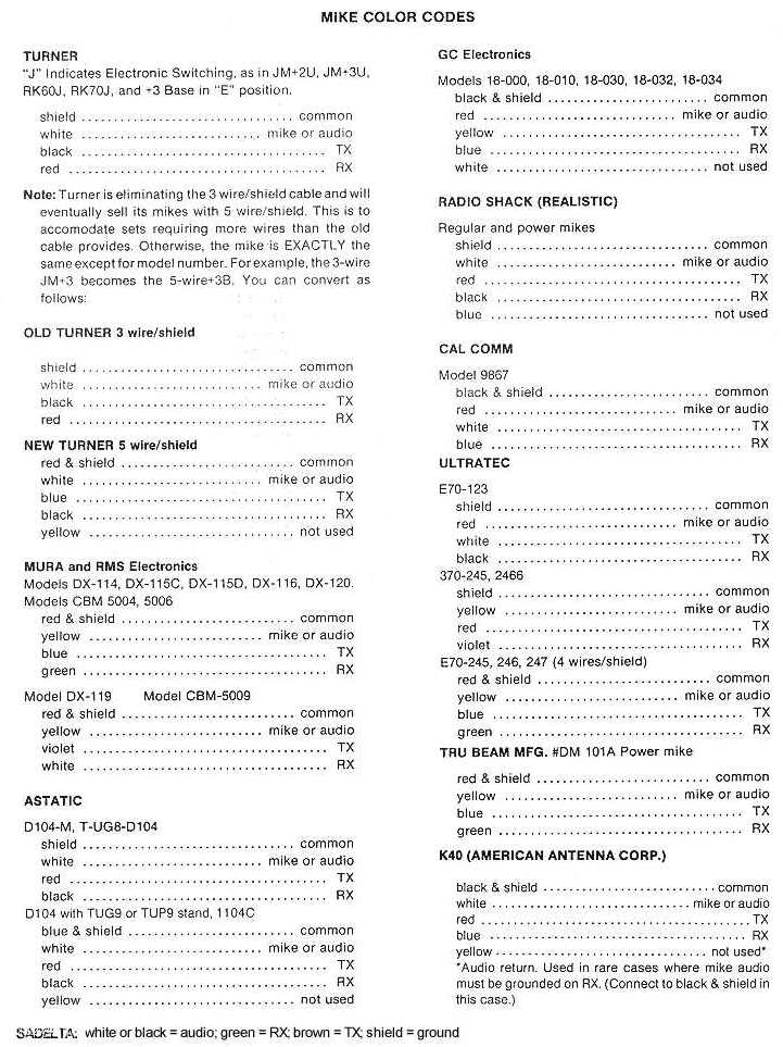
Now that you know which mike pin on the CB does what, you must match those pins to the
corresponding colored wires on the new mike. Figure 2 lists the color/function of many
common replacement mikes. If the mike brand you want to wire isn’t shown
you’ll have to figure out the color code yourself, which is very easy to do using an
Ohmmeter. (On a power mike, the battery must be installed before trying any Ohmmeter
tests.)
The typical power mike will have three, four, or five colored
wires and a shield braid. If one of the colored wires is obviously covered by the
shielded braid, it's the Mike or audio line. Otherwise if you cut back an additional
inch or so from the main cord cover, you’ll most likely see one wire that’s
wrapped with the shielded wire. Following are some typical examples.
Case #1: 3 Colors & Shield
Touch one lead of the Ohmmeter (Rx1 scale) to the shield braid and the other lead to each
color in turn. One color should show a short; i.e., 0W, when not keyed and open continuity when it is keyed. This is the RX
line. Write it down.
Another color should show a short (0W, or continuity) with the mike keyed, and open
with the mike button released. This is the TX line. The remaining color is
obviously the Mike or audio line. If you couldn’t seem to find the TX or RX
line this way, the mike is wired internally for relay switching. It will short two
of the three colored wires on TX, rather than one color and the shield braid. See
below.
The mike or audio line can be found as follows:
1. On a standard dynamic mike (not a power mike), the audio line will
normally show a DC resistance of about 300W-1000W between the shield and Mike line when keyed, on the Rx10 or
higher scale. (You may also see this in the unkeyed position.) This is
definitely the mike audio line, as the TX and RX lines will show DC resistances of 0W.
2. On a power mike with the battery installed, the resistance may vary
anywhere from a few ohms to several thousand ohms, depending on the setting of its gain
control. Many times when keying it you’ll see the Ohmmeter kick up, then slowly
settle down to a set value as the capacitors in the mike amplifier charge up.
Note: Many power mikes will show a mike line reading of a few ohms all
the time until you key it. This indicates a normally closed audio line, a
very undesirable feature. (A meter on the mike line will jump when you key
it.) A normally closed audio line can be a real problem to wire to many CBs.
It’s usually done because the manufacturer was too cheap to use a switch with enough
contacts on it to begin with. Ideally the mike line should make a complete circuit only
when you key it. All Turner mobile mikes work this way.
If you found the mike line OK, but couldn’t get an indication of TX and RX continuity
between the shield and one particular color, you have a mike that’s wired internally
for relay switching. A quick Ohmmeter check after you find the mike line will reveal
that you get a complete circuit (continuity) between the two remaining colored wires,
rather than one color and the shield.
On many mobile and most base power mikes, there’s a miniature slide switch inside the
mike or the base plate marked “E” and “R.” Put it in the
“E” for electronic position, and it will then show TX and RX continuity between
shield and colored wires. We suggest you do this even if your CB uses relay
switching. You can wire 99% of all CBs that use relay switching in the electronic
position. But the reverse is not true; a mike internally wired for relay
switching must be modified to use it on electronically switched CB radios.
Note: Turner mobile mikes don’t have the internal switch,
although some of their base mikes do. If the Turner mike starts with the letter J,
like JM+2, JM+3, etc., you’re all set up for electronic switching. Nowadays Turners
all come with 5-wire cables since relay CBs are a thing of the past, and with them the old
3-wire mike cables.
Generally speaking, it’s much better to buy a mike wired for electronic
switching. It can be easily rewired to use on another CB later just by stripping
either of the switching wires and twisting it together with the shield as a single
wire. The remaining color then becomes the TX line for relay switched radios.
You’ve reduced the four wires down to three and saved the hassle of having to open up
the mike and rewire the switch itself.
Case #2: 4 or 5 Colors & Shield
Here’s a case where the manufacturer gave you enough wires to make all the necessary
switching functions. Usually one or two of these wires will end up being unused and
can be cut off when you solder on the plug. Let’s say the mike has the
following wires in the cord:
1. Red
2. Yellow
3. Blue
4. Green
5. Shield braid.
Step #1: Identify the Mike or audio line. This will have the shield wrapped around
it. If it doesn’t, cut back another inch or so of covering; you’ll
find it. If not, use the previously described Ohmmeter method. You’re
looking for the wire that shows a kick (power mike) or a fixed resistance reading
(standard mike) between it and the shield when keyed.
Step #2: It’s very unlikely you’ll find any continuity between shield and the
remaining non-audio colored wires. Use your Ohmmeter to touch the remaining three
colors with both test probes. You should discover that two of the three colors will
short (show continuity) when keyed, and two of the three will short unkeyed. One of
those three colors is common to the other two colors, in exactly the same way we found the
common on the mike socket itself.
Step #3: Strip back that common color and twist it together with the shield, making this a
single wire. Then solder them together. You’ll now have one color left
for RX, and one color for TX, when tested for continuity with the shield.
You’ve reduced those five wires down to the four you need for electronic switching,
or the three you need for relay switching. (In this case, also cut off the
unnecessary fourth RX wire.)
To repeat as a practical example: assume from the above you discovered that YELLOW is the
Mike line, leaving RED, BLUE, GREEN, and SHIELD. You then discover that RED and BLUE
short when keyed, while GREEN and BLUE open up continuity when keyed. Therefore, BLUE is
common to both RED and GREEN. You’d then strip and twist the BLUE to the SHIELD
as one wire, leaving you with RED as TX, and GREEN as RX. (With relay switching, you
could also cut off the GREEN wire.)
Note: As previously mentioned, many regular and power mikes come
with a normally closed or shorted mike line. This can make it difficult or even
impossible to wire to certain CB radios. This problem shows up as a loud buzz, squeal, or
the receiver going dead when you plug the mike in. It’s because there
aren’t enough switch contacts to perform all the necessary functions, which include:
· connect RX or TX at the proper time.
· connect the audio line, ideally only when keyed.
· connect the power mike battery only on TX, so battery won’t
drain except when being used.
In many cases, installation of a resistor of about 4.7KW or more in series with the mike line will cure this problem. This would be
installed exactly the same way as the RF feedback squeal filter described below.
You may have to experiment to find the proper value resistor. You’ll probably
notice a slight decrease in receiver volume if it becomes necessary to resort to this
method. Use the smallest value resistor that will prevent the RX from going dead or
squealing. The mike should then work normally, and you probably won’t even
notice the volume decrease.
If you experience this problem when trying to wire certain brands of mikes, it’s
possible the mike just can’t be wired to that particular CB. For example, the Astatic
D-104 “lollipop” mike with the TUG-8 base stand uses a double pole, double throw
T/R switch. If you had this wiring problem with such a mike, you couldn’t wire
the CB to it. Instead you’d have to buy the TUG-9 stand, which uses a triple-pole,
double-throw T/R switch. (And is also more expensive.) This problem is very
rare though, and happens in maybe 5% of all mike wiring/CB combinations.
THE RF FEEDBACK “SQUEAL” PROBLEM
Note: Don’t confuse this with the “Talkback” feature of
many newer CBs. Those models are specifically designed to let you hear yourself in
the speaker so you can adjust an Echo or some other audio feature in the radio.
Feedback squeal is a very common problem. If the mike is correctly wired and there
are no broken wires in the plug or cord, the squeal is usually being caused by
RF feedback. Fancy name, easy solution. Often the stock mike works fine,
and the squeal only starts when you try to wire up a power mike.
There’s nothing wrong with the mike. RF feedback means that some of your TX
energy is getting back into the audio or modulation circuit of the CB. It starts a
continuous cycle of oscillation or feedback, just like a PA system with the mike too close
to the speaker. The most common causes are poor RF filtering in the CB, or high
antenna SWR. The cure is cheap and simple.
How To Cure The Squeal
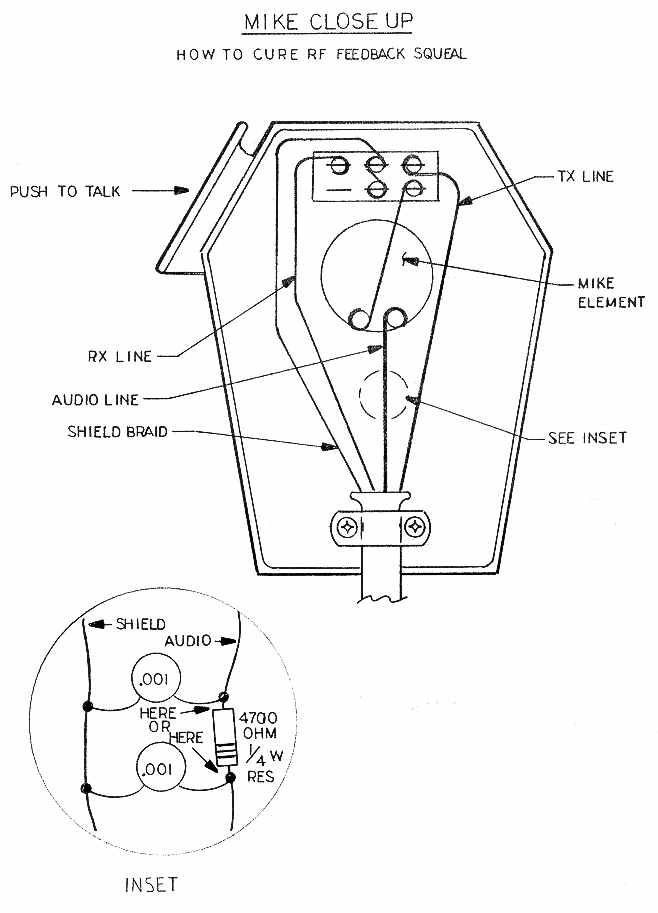
Refer to Figure 3.
1. Open the mike and figure out which colored wire is the actual audio or Mike line.
(See the previous discussion to determine this.)
2. After finding the audio line, cut it at a convenient spot and insert a 4700W (4.7KW, YELLOW-VIOLET-RED), 1/2-watt or 1/4-watt
resistor in series with the audio line. See the inset in Figure 3.
3. For extra filtering protection, also connect a .001µF or .01µF ceramic disc capacitor
from either side of your resistor/audio line connections to the bare twisted shield
(Ground) braid of the mike cable.
The value of these parts isn’t
very critical; just get the physically smallest ones you can find, like a 1/2-watt
or 1/4-watt resistor and a 50-Volt capacitor. These will easily fit inside the
mike. Solder and tape all your connections. (Please, no Scotch Tape!) These
parts together cost about 50¢, and will prevent RF energy in the TX circuits from getting
back into the mike. This works 99% of the time.
If adding the resistor only partially solves the feedback problem, you can try using a
small RF choke instead. Values of about 470µH-1000µH work well and won’t
affect the audio quality. Get the miniature epoxy type of RF chokes, which actually
look like a 1-Watt resistor and even have a 4-band color code on them. (We sell a
5-pack of 470µH chokes for $7; see address elsewhere on this Web site.)
If filtering the mike doesn't fix the problem, also check your antenna by substituting a Dummy Load. If the squeal disappears, it was caused by high SWR, which causes excess RF energy to flow back into the radio. The cure is obvious: tune or fix that antenna!
Got related questions? Contact us by email: click here.